In-wheel electric drive motors represent an effective method of providing propulsion to vehicles which otherwise were not designed to have driven wheels.
That is, they're great for EV hacking and conversion. They're compact and modular, require no support of rotating axles from the parent vehicle, and can be designed around the vehicle to be propelled. Pure DC electric hub motors, in fact, were used in some of the first electric (and hybrid electric micro motor) cars.
They are also not as complex and mystical as one might think. The advent of my project RazEr, a stock Razor scooter with a custom built electric conversion, has raised many questions from amateur EV builder looking to construct their own brushless hub motors. Until now, I have not had a single collective resource to point anyone towards, nor have I been confident enough to understand what I actually built to write about it for other hackers.
Hence, I will attempt to show that a brushless DC permanent magnet hub motor is actually relatively easy to design and build for the hobbyist, resource access considerations aside. I will first exposit some of the details of brushless DC motor theory as applied to hub motors. I will provide some thoughts and pointers about the mechanical construction of the motor itself and how to source major components. Finally, I will briefly glean over ways to control your newfound source of motion. The arrangement of this Instructable is designed for a readthrough first - because it relays theory and advice more than specific instructions on how to create one particular motor.
This is intended as a basic primer on DC brushless hub motors. Many assumptions, shortcuts, and "R/C Hobby Industry Rules of Thumb and Hand Waves" will be used. The information is purposefully not academic in nature unless there is no way to avoid it. The intention is not to design a motor that maintains above 95% efficiency across a thousand-RPM powerband, nor win the next electric flight competition, nor design a prime mover that will run at constant power for the next 10 years in an industrial process. Motor theoreticians avert thine eyes.
I will assume some familiarity with basic electromagnetics concepts in order to explain the motor physics.
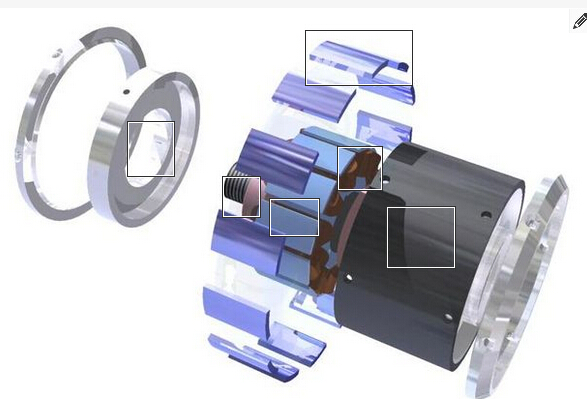
Below is an exploded parts diagram of a prototype motor that I am in the process of designing and building. Let's clear up some of the vocabulary and nomenclature immediately. The can (or casing) hold a circular arrangement of magnets (electrically called poles) and is supported on one or both ends by endcaps. This whole rotating assembly is the rotor. Internally, the stator is a specially shaped piece of laminated iron pieces (the stack) which holds windings (or coils) made of turns of magnet wire on its projections (teeth). It is stiffly mounted to the shaft (a nonrotating axle) which also seats the bearings for the rotor assembly.(dental brushless micro motorhttp://www.oyodental.com/best-Brushless-Micro-Motor-for-sale.html)
That is, they're great for EV hacking and conversion. They're compact and modular, require no support of rotating axles from the parent vehicle, and can be designed around the vehicle to be propelled. Pure DC electric hub motors, in fact, were used in some of the first electric (and hybrid electric micro motor) cars.
They are also not as complex and mystical as one might think. The advent of my project RazEr, a stock Razor scooter with a custom built electric conversion, has raised many questions from amateur EV builder looking to construct their own brushless hub motors. Until now, I have not had a single collective resource to point anyone towards, nor have I been confident enough to understand what I actually built to write about it for other hackers.
Hence, I will attempt to show that a brushless DC permanent magnet hub motor is actually relatively easy to design and build for the hobbyist, resource access considerations aside. I will first exposit some of the details of brushless DC motor theory as applied to hub motors. I will provide some thoughts and pointers about the mechanical construction of the motor itself and how to source major components. Finally, I will briefly glean over ways to control your newfound source of motion. The arrangement of this Instructable is designed for a readthrough first - because it relays theory and advice more than specific instructions on how to create one particular motor.
This is intended as a basic primer on DC brushless hub motors. Many assumptions, shortcuts, and "R/C Hobby Industry Rules of Thumb and Hand Waves" will be used. The information is purposefully not academic in nature unless there is no way to avoid it. The intention is not to design a motor that maintains above 95% efficiency across a thousand-RPM powerband, nor win the next electric flight competition, nor design a prime mover that will run at constant power for the next 10 years in an industrial process. Motor theoreticians avert thine eyes.
I will assume some familiarity with basic electromagnetics concepts in order to explain the motor physics.
Below is an exploded parts diagram of a prototype motor that I am in the process of designing and building. Let's clear up some of the vocabulary and nomenclature immediately. The can (or casing) hold a circular arrangement of magnets (electrically called poles) and is supported on one or both ends by endcaps. This whole rotating assembly is the rotor. Internally, the stator is a specially shaped piece of laminated iron pieces (the stack) which holds windings (or coils) made of turns of magnet wire on its projections (teeth). It is stiffly mounted to the shaft (a nonrotating axle) which also seats the bearings for the rotor assembly.(dental brushless micro motorhttp://www.oyodental.com/best-Brushless-Micro-Motor-for-sale.html)
 RSS Feed
